Zeroing and calibration of Crush Tester
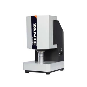
The YT-YS3000A Crush Tester is a new type of instrument developed by our company in accordance with the new national standards. The components, supporting components, and single-chip microcontrollers used in the instrument are reasonably constructed and designed with multiple functions. Equipped with LCD Chinese display, intelligent touch button operation, with various parameter testing, conversion, adjustment, display, memory, printing and other functions included in the standard. It has data processing function, which can directly obtain statistical results of various data. It also has over range protection and fault self diagnosis function.
Zero adjustment
Before the standby test, when there is no force on the upper pressure plate and the force value is not displayed as zero, click O to adjust it to zero.
The zero force value displayed on the upper pressure plate should be ± 0.1% of the measured maximum force value when there is no pressure. If it exceeds the limit, click O to zero and observe the zero drift value within 15 minutes. If it is normal, testing can be carried out.
The instrument has been calibrated before leaving the factory. When the displayed force value does not match the actual value, corresponding calibration must be carried out to ensure measurement accuracy. Click the "Settings" button to enter the parameter setting interface, then click on Image 1. png to enter the calibration interface, which displays as follows:

1) Click ↓ to suspend the upper pressure plate (without external force), click 【 Range 】 to input sensing
The standard range value of the instrument.
Note: Non professionals are not allowed to operate the following steps.
2) Place the dedicated standard force sensor in the middle of the lower pressure plate, click ↑, and stop by pressing ↑ at a distance of about 2mm between the standard sensor and the upper pressure plate. Click on "Calibration Method" to select "2 points", click on "Magnification" to switch the magnification to 128, click on "Speed" to adjust to 1mm/min, and click "O" to zero. Click ↑ again to observe the reading on the standard force measuring instrument and stop when it reaches 2000N. Then observe and compare the displayed force value of the instrument with the reading on the standard sensor head. If the error is ± 0.5%, the calibration is completed. Otherwise, continue to the next step.
3) Click on [Force Value], enter the standard value to match the displayed value on the standard force gauge, click on Image 3. png, enter the password 3215 to confirm saving, and then click ↓ to remove the pressure.
4) Click ↑ again to reach 20%, 40%, 60%, 80%, and 100% of the maximum range of the instrument
Compare whether the pressure error at each point meets the accuracy of ± 0.5%. If it meets the requirements, the calibration is completed. Otherwise, click on 【 Magnification 】 to switch the magnification (from large to small) and repeat the above steps. If it still does not meet the accuracy range, please contact after-sales service.
Calibration pressure plate distance
Adjust the pressure plate to the appropriate distance, use a vernier caliper to measure the actual values of the four points between the upper and lower pressure plates, calculate the average value, and input it.
Protection control
1) During the testing process, if the force value exceeds 10% of the full range, it will prompt an overload of the test force value and the lower pressure plate will automatically stop. At this point, click ↓ to release the pressure and avoid damage to the force sensor.
2) During the testing process, when the lower pressure plate touches the limit position, the upper pressure plate immediately stops moving. At this time, you can press the ↓ key to leave the limit position.